A month ago, finally got myself my first 3D printer, a modest Ender 3. Not the point of this post, but a very very nice cheap machine, after a quick 30min assembly without any troubles, I had the printer ready and working almost flawlessly, after one or two calibration print, very nice results.
The problem
After a week of honeymoon, printing random stuff from thingiverse, and inserts for my board game collection, one day I walk to my printer halted with a error on the screen: Thermal runaway PRINTER HALTED. Ok, that’s bad. This being my first 3d printer, I go and google wtf is a thermal runaway, after a few minutes I have a superficial idea.
Basically, The printers is trying to heat, turning the heat element on, but it don’t see a change of temperature on the sensors, this can be that the heating element it’s not working, or worse, the sensor is faulty and the machine keep heating, causing a potential fire. As a safety feature, the printer stops, but this problem can happen to the nozzle heater or the bed heater and the original ender 3 firmware don’t give me this info.
Installing marlin
During the first week with the printer, I didn’t thinker with it, it was working and I was having, and being a cheap hobbyist machine, sooner or later I’ll end up modifying it, well, the time came.
With the original firmware not giving me the info on what caused the thermal runaway, my next step was installing Marlin, the process is pretty straight forward if you have some experience with embedded systems, clone the repository, use the config files for the ender, build with platformio.
New firmware installed, I did some more prints, and catch the problem again, this time with a valuable information: E1 Heating failed. Ok, now I know that the problem it’s on the hotend.
First round of debug
Another quick search, I gather on the internet the main causes of thermal runaway
- Thermistor too tight on the heating block
- Bad connections on the thermistor or heating element
- Bad thermistor
- Bad heating element
- Bad power supply
- Faulty control board
Verified all of the items, monitored the voltage during print, measured the resistance of the heating element and thermistor, did all the connections again, the only issue that I could not eliminate was the faulty main board, as this is my only printer.
Did some more prints, and the error happened again…
Installing octoprint and gathering more data
Installed octoprint with docker on my laptop, and started monitoring my prints. Octoprint give us a nice graph of temperatures, and was a invaluable tool to debug this.
Did a couple of prints, and started to notice a pattern, the prints normally start with the temperatures pretty stable, like so: 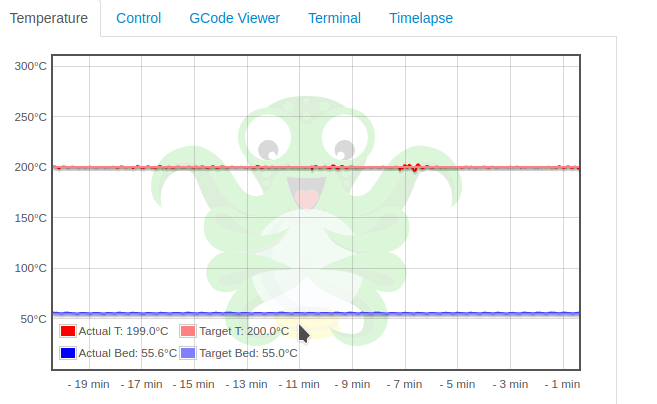
But after the first layers, when the printer stop doing the skin slowly and start moving pretty erratic, the temperature oscillates a lot. 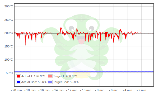
Finally I could catch the error, the following images show the log and the graph on the thermal runaway. 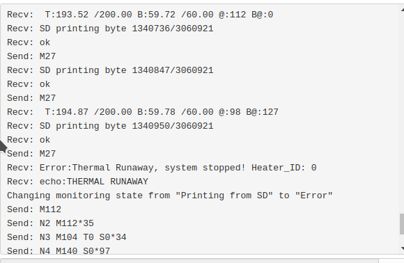
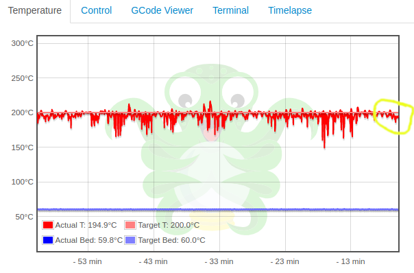
As can be seem in the yellow circle, the temperature read dropped and did not recover to the target temperature in the specified time, triggering the runaway.
With this information we can infer some things. The is NO WAY my readings were precise, those 50 degrees temperature dips are impossible.
The temperature sensor is a simple NTC thermistor, a 100k resistor that decreases its resistance with the increase of the temperature. This is achieved by creating a voltage divider with another resistor, and reading the voltage on a analog input of the microcontroller, as shown in this part of the reprap rambo board. 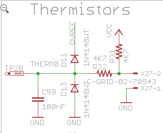
With this in mind, we can speculate two major reasons why this is happening, something is happening with the thermistor end, damaged cable, damaged thermistor, electromagnetic interference, bad solder joint on connection, etc. On the other hand something really bad is going on the control board.
Again, I didn’t have any spare parts to test with, so I proceeded with the thermistors investigation. Also, a problem with interference in the reading is not probable, this is a common printer, and it’s not a know issue, and the spikes on the graph are way more pronounced on the temperature dip, not the random oscillation you would expect on electromagnetic noise.
With these dips in mind, if there is a bad connection on the thermistor, it would cause a open circuit, meaning the microcontroller would read a max voltage from the other resistor in series, causing a low temperature read. But this temperature would be way lower than 150 degrees, this should trig a ‘MINTEMP’ error, as you can se in the code bellow. But if we analyze a part of the marlin firmware code, we can see the reads are sampled.
  /**
   * One sensor is sampled on every other call of the ISR.
   * Each sensor is read 16 (OVERSAMPLENR) times, taking the average.
   *
   * On each Prepare pass, ADC is started for a sensor pin.
   * On the next pass, the ADC value is read and accumulated.
   *
   * This gives each ADC 0.9765ms to charge up.
   */
  #define ACCUMULATE_ADC(obj) do{ \
    if (!HAL_ADC_READY()) next_sensor_state = adc_sensor_state; \
    else obj.sample(HAL_READ_ADC()); \
  }while(0)

  ADCSensorState next_sensor_state = adc_sensor_state < SensorsReady ? (ADCSensorState)(int(adc_sensor_state) + 1) : StartSampling;

  switch (adc_sensor_state) {

    case SensorsReady: {
      // All sensors have been read. Stay in this state for a few
      // ISRs to save on calls to temp update/checking code below.
      constexpr int8_t extra_loops = MIN_ADC_ISR_LOOPS - (int8_t)SensorsReady;
      static uint8_t delay_count = 0;
      if (extra_loops > 0) {
        if (delay_count == 0) delay_count = extra_loops;  // Init this delay
        if (--delay_count)                                // While delaying...
          next_sensor_state = SensorsReady;               // retain this state (else, next state will be 0)
        break;
      }
      else {
        adc_sensor_state = StartSampling;                 // Fall-through to start sampling
        next_sensor_state = (ADCSensorState)(int(StartSampling) + 1);
      }
    }

    case StartSampling:                                   // Start of sampling loops. Do updates/checks.
      if (++temp_count >= OVERSAMPLENR) {                 // 10 * 16 * 1/(16000000/64/256)  = 164ms.
        temp_count = 0;
        readings_ready();
      }
      break;

    #if HAS_TEMP_ADC_0
      case PrepareTemp_0: HAL_START_ADC(TEMP_0_PIN); break;
      case MeasureTemp_0: ACCUMULATE_ADC(temp_hotend[0]); break;
    #endif

    #if HAS_TEMP_ADC_BED
      case PrepareTemp_BED: HAL_START_ADC(TEMP_BED_PIN); break;
      case MeasureTemp_BED: ACCUMULATE_ADC(temp_bed); break;
    #endif
/**
 * Convert the raw sensor readings into actual Celsius temperatures and
 * validate raw temperatures. Bad readings generate min/maxtemp errors.
 *
 * The raw values are generated entirely in interrupt context, and this
 * method is called from normal context once 'raw_temps_ready' has been
 * set by update_raw_temperatures().
 *
 * The watchdog is dependent on this method. If 'raw_temps_ready' stops
 * being set by the interrupt so that this method is not called for over
 * 4 seconds then something has gone afoul and the machine will be reset.
 */
void Temperature::updateTemperaturesFromRawValues() {

  watchdog_refresh(); // Reset because raw_temps_ready was set by the interrupt

  TERN_(TEMP_SENSOR_0_IS_MAX_TC, temp_hotend[0].raw = READ_MAX_TC(0));
  TERN_(TEMP_SENSOR_1_IS_MAX_TC, temp_hotend[1].raw = READ_MAX_TC(1));
  TERN_(TEMP_SENSOR_REDUNDANT_IS_MAX_TC, temp_redundant.raw = READ_MAX_TC(TEMP_SENSOR_REDUNDANT_SOURCE));

  #if HAS_HOTEND
    HOTEND_LOOP() temp_hotend[e].celsius = analog_to_celsius_hotend(temp_hotend[e].raw, e);
  #endif

  TERN_(HAS_HEATED_BED,     temp_bed.celsius       = analog_to_celsius_bed(temp_bed.raw));
  TERN_(HAS_TEMP_CHAMBER,   temp_chamber.celsius   = analog_to_celsius_chamber(temp_chamber.raw));
  TERN_(HAS_TEMP_COOLER,    temp_cooler.celsius    = analog_to_celsius_cooler(temp_cooler.raw));
  TERN_(HAS_TEMP_PROBE,     temp_probe.celsius     = analog_to_celsius_probe(temp_probe.raw));
  TERN_(HAS_TEMP_REDUNDANT, temp_redundant.celsius = analog_to_celsius_redundant(temp_redundant.raw));

  TERN_(FILAMENT_WIDTH_SENSOR, filwidth.update_measured_mm());
  TERN_(HAS_POWER_MONITOR,     power_monitor.capture_values());

  #if HAS_HOTEND
    static constexpr int8_t temp_dir[] = {
      #if TEMP_SENSOR_IS_ANY_MAX_TC(0)
        0
      #else
        TEMPDIR(0)
      #endif
      #if HAS_MULTI_HOTEND
        #if TEMP_SENSOR_IS_ANY_MAX_TC(1)
          , 0
        #else
          , TEMPDIR(1)
        #endif
        #if HOTENDS > 2
          #define _TEMPDIR(N) , TEMPDIR(N)
          REPEAT_S(2, HOTENDS, _TEMPDIR)
        #endif
      #endif
    };

    LOOP_L_N(e, COUNT(temp_dir)) {
      const int8_t tdir = temp_dir[e];
      if (tdir) {
        const int16_t rawtemp = temp_hotend[e].raw * tdir; // normal direction, +rawtemp, else -rawtemp
        if (rawtemp > temp_range[e].raw_max * tdir) max_temp_error((heater_id_t)e);

        const bool heater_on = temp_hotend[e].target > 0;
        if (heater_on && rawtemp < temp_range[e].raw_min * tdir && !is_preheating(e)) {
          #if MAX_CONSECUTIVE_LOW_TEMPERATURE_ERROR_ALLOWED > 1
            if (++consecutive_low_temperature_error[e] >= MAX_CONSECUTIVE_LOW_TEMPERATURE_ERROR_ALLOWED)
          #endif
              min_temp_error((heater_id_t)e);
        }
        #if MAX_CONSECUTIVE_LOW_TEMPERATURE_ERROR_ALLOWED > 1
          else
            consecutive_low_temperature_error[e] = 0;
        #endif
      }
    }

  #endif // HAS_HOTEND
This mean that if the connection is lost by a couple of milliseconds, this bad low temperature reading is wrongly taken in account, dropping the reading average. The spikes above the target temperature is caused then by the PID, overshooting the temperature trying to compensate the measured low temp.
Fixing the issue
With all this in mind, and with a strong mechanical influence in the bad readings (moving the cable sometimes stopped the oscillation, and the print almost always would keep a constant temperature while doing the first layers slowly), I decided to simple pull out the thermistor and mount it externally, like so:
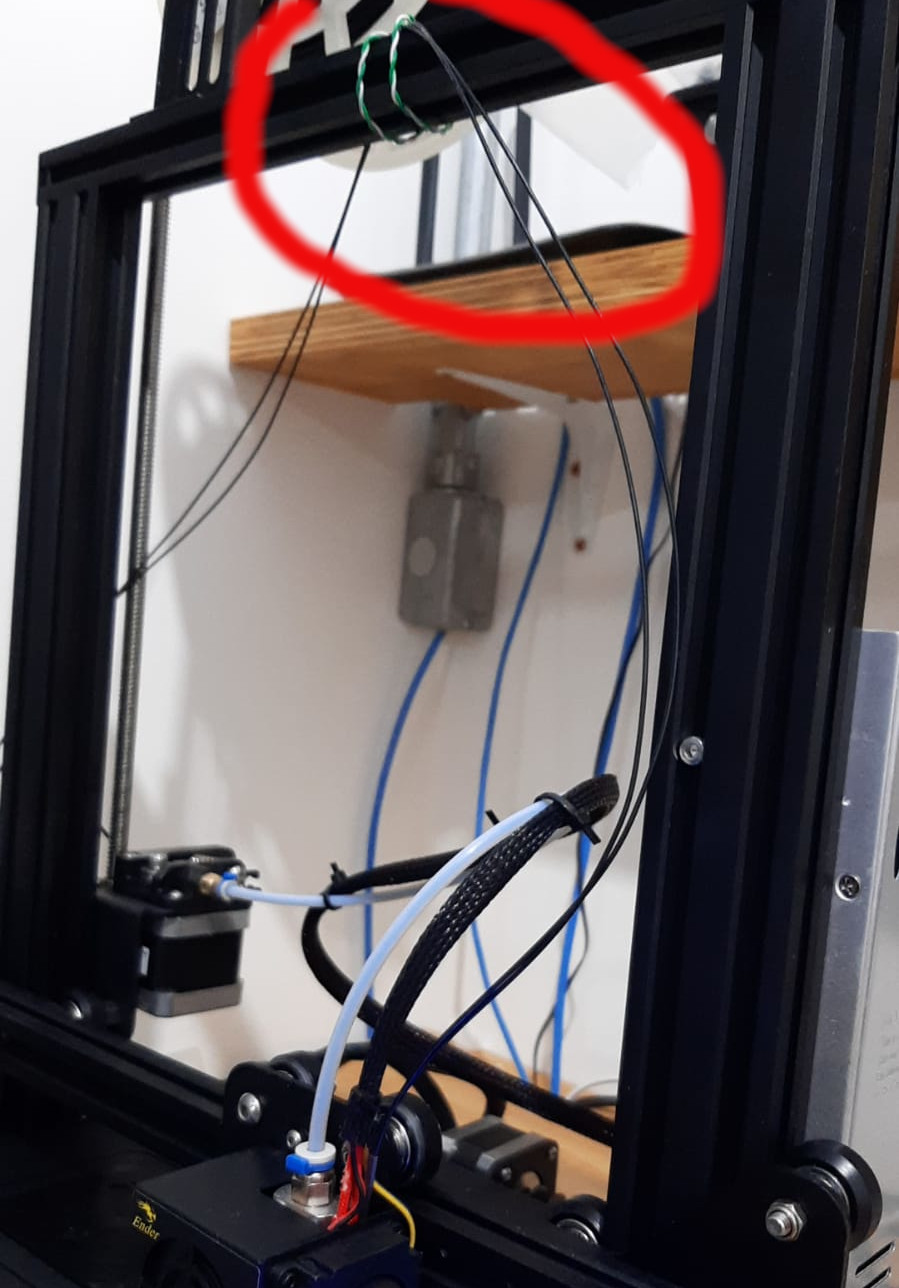
And, there you go, problem solved ! Hot end temperature perfectly stable, 0.1 oscillations without a new PID tune. Did a 12h print, no problem !
I contacted the seller, and after explaining that I already did all the debug, and I was sure this was a thermistor problem, they then sent me a new one. Installing the new one was kind of cumbersome, those cable sleeves are a pia, but with some patience and someone help, was a 15min job.
But here’s the thing, after installing the new thermistor, I took the faulty one to the bench and connected it to my oscilloscope, trying to find where the cable was broken. Well, I could not replicate the issue… banged the wire on the table, bend it all the way, nothing, solid readings. I will come back to this sometime, but this might show that my hypothesis was all together wrong, and I fixed it by accident, but it makes no sense, a bad solder joint ? A really really tiny fracture in the cable that happens only in a very specific way ? Who knows…